E-transmission
E-transmission objective
The objective of the workspace related to the E-transmission is to systematically study the entire drivetrain (battery pack, inverter and electric machine) through Hardware-in-the-Loop (HiL) simulations. The main focus areas include energetic performance studies with comparisons between simulations and real vehicle testing (such as the Nissan Leaf). Multiple test benches are available to address various criteria for scientific research, such as implementing electric drive control with experimental validation of the electric drive behavior, or validating the electric drive behavior under different energy management strategies based on various real-time optimization methods.
The test bench is also used for a wide range of ancillary applications:
- Driver-in-the-Loop Simulation paired with the drivetrain testing to studies impact of human behavior
- Caractherisation and loss mapping using a power analyzer (HBK)
- Development and validation of real-time simulation models with management for different case studies
- Distributed HiL Simualtion (Cloud or direct link)
- Software Define Vehicle (SDV) application
- Etc.
Example of available test bench: Nissan Leaf bench
The test bench activity enables of Hardware-in-the-Loop (HIL) testing for electric drive across various themes. The inverter and the actual electric machines from the Nissan Leaf are mounted head-to-tail with a second electric drive. The inverter of the electric drive can be connected either through a DC load or via the actual battery pack of the Nissan Leaf, depending on the goals intended for the experimental tests. The charger of the Nissan Leaf is also present to charge the battery pack connected above the inverter. The real communication network of the Nissan Leaf is artificially reproduced through the dSPACE real-time simulation platform to enable real-time control of the machine.
The figure (Fig. 1) below shows the macroscopic organization of the Nissan Leaf test bench in its standard configuration ( Fig. 2 - Table. 1). It possible to observe the electric drive (with or without its battery) and the load electrive drive. The inverters of each electric drive communicate with a dSPACE real-time simulation platform (Scaxelio). The real-time platform emulates the real-life communication of the Nissan leaf vehicle, and enables different simulation models to be set up with energy management. Tests are based on different normalized/real driving cycles, or connected directly to a driving simulator. In this way, it is possible to observe the behavior of the electric drive by making it believe it is actually in the system, in order to observe its behavior in the system as a whole.

Organisation between sub-system tested, emulator interface and real time platform (model) for electric drive testing
Drivetrain under test is composed of :
- Voltage Power source
- Three-phase inverter
- Synchronous electric machine (permanent magnet)
- Its ECU (Drivetrain Control)
Load drivetrain under test is composed of :
- Voltage Power source
- Three-phase inverter
- Synchronous electric machine (permanent magnet) with its control
- Torque Sensor
The drivetrain load represents the emulation interface that represents the behavior of the real-time model on the powertrain under test.
The real-time simulation platform enables the mechanical part of the vehicle in purple (with its control in blue) to be simulated in real time, as it is not physically available.
The real-time platform exchanges data via CAN BUS communication between the emulation interface and the powertrain under test.
The test allows the drivetrain to be tested, taking into account the effect of the overall system through a real-time model, in order to observe its behavior and validate the control or not.

The figure give an global overview of the setup with :
On the right side : The electric drive test benches with electrical machine and inverter
On th left side : The water cooling system with its fan
| Characteristic E-drive | Value |
|---|---|
| Model | EM57 |
| Electric machine type | IPMSM |
| Power supply | 3 phases |
| Voltage | 360V |
| Rated power | 86kW |
| Maximun power | 110 kW @ 3283 - 9795 rpm |
| Maximun torque | 320 Nm @ 0 - 3293 rpm |
| Maximun speed | 10500 rpm |
| Model | EM57 |
| Characteristic battery | Value |
| Nominal voltage | 350 V |
| Capacity | 112.4 Ah |
| Energy | 39.4kWh |
Contact
Prof. Walter Lhomme,
Walter.Lhomme@univ-lille.fr,
University of Lille
Project linked to Drivetrain
Can you imagine the number of transport applications that need to be electrified to meet the increasingly stringent emissions standard? Have you thought about the diversity of technical solutions, along with the time and effort required to find the optimal solutions for each transport application? In this sense, reducing the development time of electric vehicles becomes an urgent priority at the forefront of the automotive industry's agenda. For this aim, new methodologies and tools, supporting the exploration of the system-level design space, are required. These methodologies should allow for assessing different sizing choices of electrified powertrains in the early development phases, both efficiently in terms of computational time and with reliable results in terms of energy consumption.
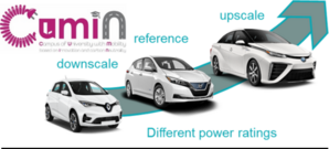
In this perspective, the STeVE project (Scalability of powerTrain of electrified Vehicles of an Eco-campus), aims to contribute to reducing the time-to-market of electric powertrains by developing new methodologies based on the scalability approach. This project is carried out jointly within an international collaboration between the University of Lille and Ghent University in Belgium. The scaling procedure is aimed at predicting the data of a newly defined design of a given component of the powertrain with different specifications based on a reference design, without redoing the traditional time and effort-consuming steps.
The research activities, within the framework of STeVE, have yielded significant insights and a comprehensive understanding of the scaling of electrified powertrains. Currently, the developed set of tools comprises:
- Different derivations of scaling laws of powertrain components, e.g. voltage source inverter, electric machine, and gearbox, validated based on either numerical campaign or experimental campaign.
- Flexible simulation tools for different power-rated vehicles: this approach includes scalable models (static or dynamic) and control of powertrains. This is achieved based on keeping a reference model and control of the powertrain fixed (due to security considerations to protect your source code if access to the reference models may be restricted), but complemented with power adaptation elements at the electrical and mechanical sides to consider the scaling effect.
- Holistic design methodology: the scaling approach considers the interaction between the scaled components to guarantee optimal powertrain performances
Reliable energy consumption quantification of various electrified vehicles with different power ratings, ranging from light to heavy-duty vehicles.
CUMIN program : https://cumin.univ-lille.fr/
Partners

Funders