
E-infrastructure
Infrastructure workspace objective
The primary focus of the Infrastructure workspace revolves around electric vehicle charging infrastructure. It is encompassing of slow, medium, and fast charging charger, with a particular emphasis on their efficiency and their impact on vehicle battery aging. The vehicles under studies in this context are the Nissan Leaf and the Tazzari Zero.
The second important aspect concerns the energy infrastructure of guided transport systems (e.g. the infrastructure of a metro line). The aim is to increase the efficiency of the entire system, for example by improving regenerative braking, which is generally limited by the non-reversible nature of the power substations. Various solutions are being studied, such as adjusting traffic or vehicle speed profiles, integrating energy storage options such as batteries, setting up reversible power substations or adding electric vehicle charging stations at parking stations connected to the main infrastructure.
This workspace covers the following topics :
- Energy management (optimization)
- Sizing
- Cost-effective energy-saving measures
- Modelling and forecasting energy consumption
Example of test benches for e-infrastructure
The "e-Infrastructure" workspace is dedicated to supply infrastructures of various e-vehicles: PV-based charging station for e-bike, fast charging station to e-car (Table 1) and traction power supply for subways and trains (Fig.1 and Table 2). This last part is the most innovative of the platform that is described below. The main objective of the "e-Infrastructure" workspace is to test innovative solutions of charging or supply systems of various electrified vehicles.

The figure shows the various links between the metros, the metro station and the line resistance. The line resistance is adapted in real time according to the metro's evolution, thanks to a specific system developed on the eV platform. Substations are fed directly from the network, and subways are simulated in real time using a real-time model.
The experimental set-up consists of real power components/subsystems and simulated virtual components/subsystems based on Power Hardware-In-the-Loop (P-HIL) technique (Fig 2). The simulation and control parts are implemented in a MicroLabBox using dSPACE. Models and controls are implemented on Matlab-Simulink and are organized using Energetic Macroscopic Representation (EMR).
")
The figure shows the link between the hardware part (test bench) and the software part. The test bench was presented earlier, and the figure shows the transmission model for driving the emulation interface (power amplifier). The magenta part represents the transmission model and the blue part the control.

| Charger | Ev box Fast charger |
|---|---|
| Power | 50 kW |
| Voltage | Until 800V |
| Plug type | Chademo, Combo 2, Plug Type 2 |

| Subway platform | Features |
|---|---|
| Number of station | 3 substation emulated |
| Number of subway | 6 |
| Power sacle | 1/1000 |
Contact
Associate Professor Phillipe Delarue,
Phillipe.Delarue@univ-lille.fr,
University of Lille
Project linked to Infrastructure
Recovery of Metro Braking Energy for a Sustainable University
REMUS is a joint project between the European Metropolis of Lille (MEL) and L2EP, within the framework of the CUMIN demonstrator program at the University of Lille. The objective is to study various innovative solutions for improving the energy efficiency of the rail transport system of MEL. More specifically, the "Cité Scientifique" campus of the University of Lille is served by 2 metro stations, with nearby parking lots and a bus hub. This configuration would make efficient use of the metro's braking energy to power and meet the growing energy demand of nearby electric vehicle charging stations (including electric buses), thus contributing to the development of a campus based on e-mobility.
The REMUS project comprises two interconnected parts:
- The development of specific energy simulation tools to assess energy flows in the rail system, integrating potential energy-saving technologies (energy storage systems, reversible traction substations, EV charging stations, etc.).
- The development of a reduced-scale hardware-in-the-loop experimental platform, enabling simulation models to be validated and new innovative concepts to be tested experimentally before being integrated into the real system.
The REMUS project focuses on these two aspects, working to improve the energy efficiency of the metro system and targeting significant reductions in energy consumption and greenhouse gas emissions. Consequently, the strategies and technologies developed and implemented as part of the REMUS project could serve as a model of sustainable mobility for other campuses and cities wishing to reduce their carbon footprint.

The test bench emulates line 1 of the Lille metro at reduced power. It allows real-time emulation of the evolution of subways on the line, by adapting the line resistance between substations as a function of distance. In this way, power exchanges can be measured and analyzed in real time to propose energy management and test technical solutions to reduce energy consumption.
At the same time, real metro tests can be carried out on a portion of the line to compare results and improve HiL tests.
The experimental set-up consists of real power components/subsystems and simulated virtual components/subsystems based on Power Hardware-In-the-Loop (P-HIL) technique. An interface (power amplifier) is used to guarantee seamless interaction between the 2 environments (real and virtual). A subway vehicle is modeled (purple elements) and simulated in real time, along with its control and braking strategy (blue elements), while real power components are used for the power supply system: Traction Power Substations (TPS) and Local Power Supply System (LPSS) (rail or catenary). In this case, a power amplifier (yellow element) is used to 1) feed the simulation model with the voltage measured on the real power system and 2) reproduce on the hardware part the current that is absorbed by the vehicle (estimated in simulation). The experimental platform has been designed to be flexible and is currently able to consider up to 3 TPS and 6 vehicles. Real components are used for the TPS considering a reduced-power scale compared with a real public transport system. The LPSS is reproduced using an intelligent relay system specially designed to take account of vehicle movements. Finally, the vehicles are modelled and simulated in real time considering the full-scale power. Power adaptations are introduced between virtual (full-scale power) models and real (reduced-scaled power) components. The simulation and control parts are implemented in a MicroLabBox using dSPACE. Models and controls are implemented on Matlab-Simulink and are organized using Energetic Macroscopic Representation (EMR).

A description of the various elements is given below:
- TPS is the substation (metro station)
- LPSS is the metro line (line 1)
- DC bus is the inverter power supply
- Power AMP corresponds to a power amplifier used to control the current supplied by the transition and auxiliary models.
- The transmission and auxiliary models are simulated in real time on the dSPACE platform.
- Metro control is also carried out in the dSPACE platform
- The external controller manages the experimental test (power section)
All step are interconnected and necessairy datas are echanged to perform correctly the test.
Partner

Funders

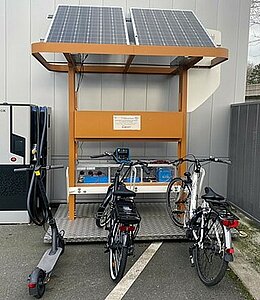
Autonomous charging stations of light e-Mobility for low environmental Impact
SAMI (Study of Autonomous charging stations for light e-Mobility with low environmental Impact) is a project under the CUMIN (Campus of University with Mobility based on Innovation and carbon Neutral) program.
The station, completely off-grid and powered solely by solar panels, is designed to recharge electric bicycles and scooters. This setup provides the project with flexibility in terms of usage, location, and sizing.
Partner

Funders
